Working with CAN bus
Selecting and connecting to the interface
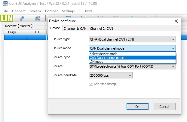
Click Settings
- Device type – your CAN-Hacker interface type
- Device mode – CAN, LIN, CAN+LIN device mode.
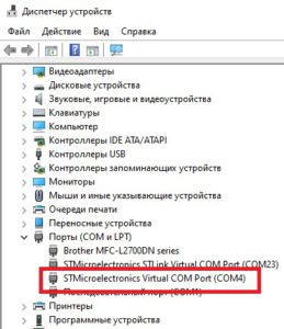
- Source – Virtual COM Port (See in the Windows Device Manager)
CAN Baudrates
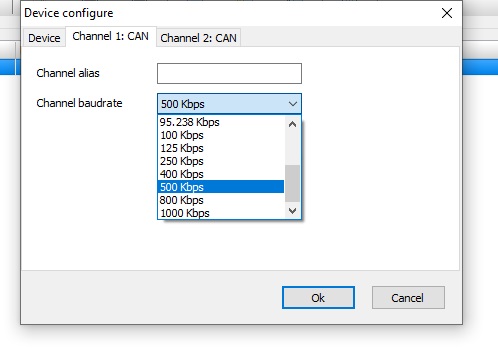
- Cnannel alias – User’s channel name
- Channel baudrate – standart CAN baudrates
- Custom baudrate – user defined CAN baudrate
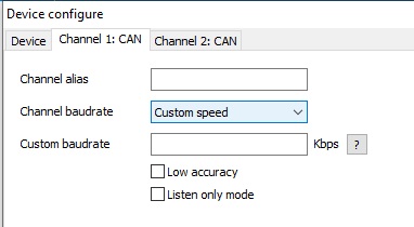
If you want to use a Custom CANbus baudrate:
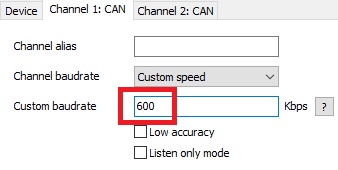
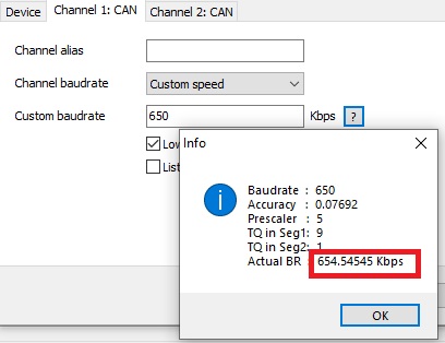
Custom baudrate – enter the required CAN speed. Once the speed is entered, an attempt will be made to calculate the CAN controller clock divisor. If the clock divisor is an integer, then the input value will be displayed on a white background and after pressing the OK button, the CAN channel will run at the specified speed.
If the entered baudrate doesn’t allow the integer divisor to be calculated, the value entered will be highlighted in red.
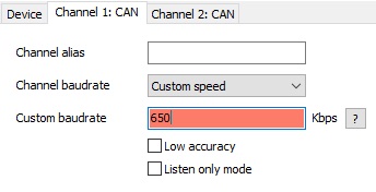
In this case it is necessary to set the Low accuracy flag and CARBUS Analyzer will set the CAN channel speed as close as possible to the entered value.To know the estimated approximate value, press the button “?”
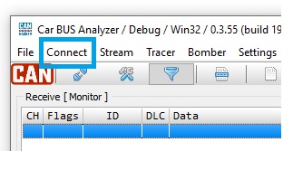
After configuring the CAN adapter and CAN channels in the top menu, click Connect
CAN Frames receiving
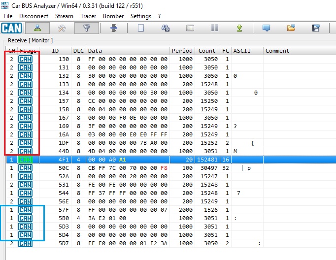
If CAN-Hacker is connected to one or two CAN buses and the speed of CAN is determined correctly, the physical connection to the CAN bus is correct and there is activity on the bus, then you will see the frames passed across the bus in the receiving window because in the image below.
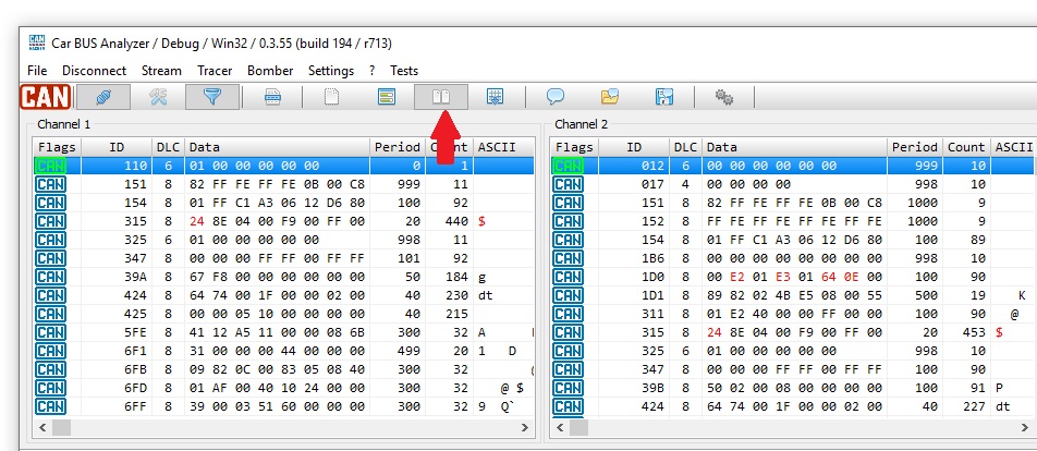
For the convenience of analyzing data transmitted through different channels, click the Splitter button in the top menu (the arrow on the photo above) and the data of each channel will be displayed in its own window.
CAN Frames transmitting
To transfer CAN frames in the Transmit window, click the Add button and form the required frame. You can select a channel, type ID 11 or type 29 bits, and the batch time when you press the Run button. For a single send, press Shot. In addition, right-click on the Transmit window – You can perform group operations – Run All and Stop All, as well as save and load the transferred frames into a file.
The Shot button sends the selected frame once.
![]()
Triggers for automatic frames transmit.
You can set the trigger for each message for automatic transmission.
In this case the transfer will start only if the frame specified in the trigger settings is accepted.
In the screenshot above, the trigger is configured as follows:
If CAN channel #2 accepts a frame with:
- ID=0x123
- DLC=8
- Data:12 34 56 78 12 34 56 78
CAN channel #2 will transmit frame:
- ID=0x321
- DLC=8
- Data: 87 65 43 21 87 65 43 21
In this example, channels #1 and #2 were combined physically for illustration, so the automatically sent frame via channel #2 we see accepted in channel #1. The trigger is activated by click the RUN button on the selected frame.

Bit fields
Frames can be presented as a bit field, which is convenient, for example, when searching for binary signals such as:
- open\closed doors
- lights turned on\off
- Control indicators status
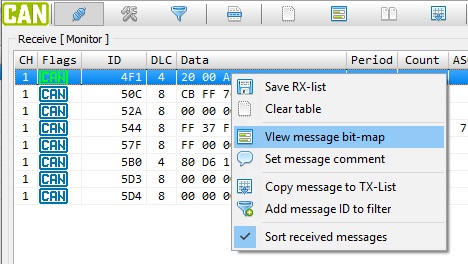
To present a frame as a bit field, right-click on the frame and click on Message bit-map in the context menu
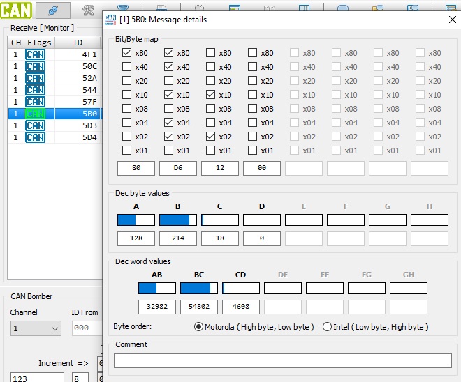
After which the window with the bit field of the selected frame appears
Frame IDs filters
The CARBUS Analyzer software allows working with both hardware filters of CAN frames and with a software filter on a given ID range.
Hardware filters differ in that they work directly in the CAN interface controller and do not affect program and firmware speed.
The program filter works in the CARBUS Analyzer program itself, so in this case the program receives from the interface the entire flow of data from the CAN bus and if this flow is dense, it can affect the speed. However, it is much easier to configure the software filter. You only need to set the ID range that you want to accept.
Hardware CAN filters have priority over the software filter!
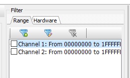
Hardware filters are on the Hardware Filter Table tab. The Program Filter over the ID range is on the Range tab.
Hardware ID filters
Use the tab on the right side of CARBUS Analyzer to work with CAN filters. If you are using a small screen monitor, click the funnel icon at the top of the program menu to call the filter configuration window.
For two-channel CAN interfaces, the filters 0 through 12 belong to CAN channel 1. Filters 13 through 28 belong to CAN channel 2.
For single-channel interfaces (e.g., CH-OBD.M02), all 28 CAN filters belong to the same CAN channel.
The matching of filters and CAN channels is shown in the CH column of the filter table.
Each filter and mask can be either 11 bits or 29 bits. Select the right type based on which type of ID you want to add to the table.
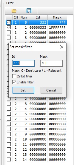
To configure the filter, double-click it, which will open the configuration window of the selected filter.
If you want to use 29 bit – set flag 29 bit filter
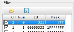
After setting the mask and filter code, set the Enable Filter flag and press Set. In the filter table, the active filter will be selected by the flag in front of it.
The filter can be switched off quickly by manually removing the flag from the filter.
You can also enter the desired ID in the filter table from the Receive Monitor window or the Stream window.
To do this, right click on the ID and click on Add message ID to filter in the context menu
Hardware filter value setting principle
The principle of CAN filters is that the mask bits indicate which bits of the inbound filter ID must be accounted for, and the value of the filter code (Filter field) indicates that these masked bits must be equal.
Example:
ID = 7E0 HEX 111 1110 0000 BIN
Mask = 7FF HEX 111 1111 1111 BIN
In this example, we tell the CAN controller that it is necessary to account for all 11 bits of the accepted ID, and these bits must be equal to = 111 1110 0000 BIN or 7E0.
Thus the filter will be configured to receive only frames with ID=7E0.
If in this example, in the mask value, replace the last four bits with zeros, the mask takes the form Mask = 7F0 HEX 111 1111 0000 BIN , we tell the CAN controller that we are not interested in the last four bits (half bytes) adopted ID and will accept all ID frames from 7E0 to 7EF.
If you set the mask and filter to 0000000000, all frames will be accepted. If at least one CAN filter of the channel is configured in this way, the other filters of this channel will have no effect.
Other examples are as follows:
Skip only frames with ID =0x7E8
ID = 7E8 HEX 111 1110 1000 BIN
Mask = 7FF HEX 111 1111 1111 BIN
Skip all ID frames with a ninth bit=1
(1xx, 3xx,5xx, 7xx, where xx-any number from 0 to FF)
ID = 100 HEX
Mask = 100 HEX
For 29-bit ID, the logic is the same, with filter and mask lengths becoming 29-bit.
For example:
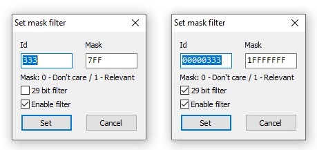
Skip only frames with 29-bit ID = 0x0000000333:
ID = 0x0000000333
Mask = 1FFFFFFF
It is important to understand that the type of filter (11 or 29 bits) depends not on the value of the filter or mask, but on the special flag set by the CAN controller, the poet ID can be:
0x000333 – 29 bits
0x333 – 11 bits
IMPORTANT: If all filters are disabled, the first filters of each CAN channel are configured to pass all incoming frames.
Working with ID-range software filter
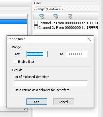
To configure the program filter to the ID range, you must enter the Range tab of the filter table.
Double-clicking the right mouse button on the selected channel filter opens the configuration window.
The range of identifiers to be ACCEPTED is set in the fields From – the initial ID of the range and To – the end point of the range. All frames with an ID from a given range will be accepted.
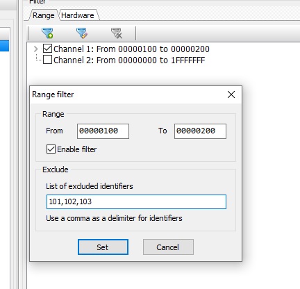
The Exclude field specifies the ID that SHOULD NOT be received in the range above.
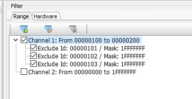
On the screenshot above, the range of ID from 0x100 to 0x200 is set. However, frames with ID equal to 0x101,0x102,0x103 will not be accepted.
After the filter is configured, press the SET button and the filter will be activated.
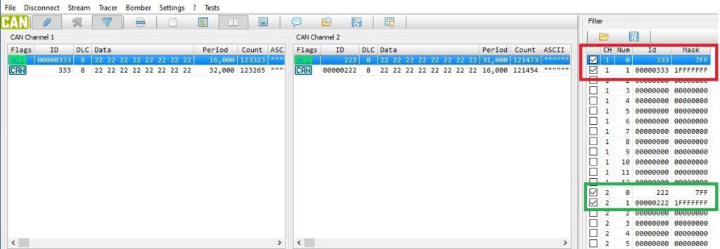
In the example below, the CAN-1 channel accepts frames transmitted by the CAN-2 channel according to the configured software filter.
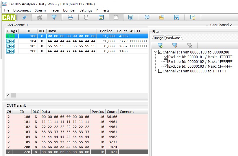
IMPORTANT: The program range filter does not distinguish between 11 bit and 29 bit Ids. Therefore, if you set the range 0x222…. 0x333, then frames with ID in the range 0x00000222,,, 0x00000333 will also be accepted.
Working with Traces
To record a stream (Trace), click the top Stream menu
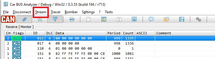
In the window that opens, you will be able to record the flow of CAN frames sequentially.
- Red circle button – Start recording CAN frames.
- Blue square button – Stop recording
The red circle button takes the form of a blue square button after the beginning of the recording and vice versa)
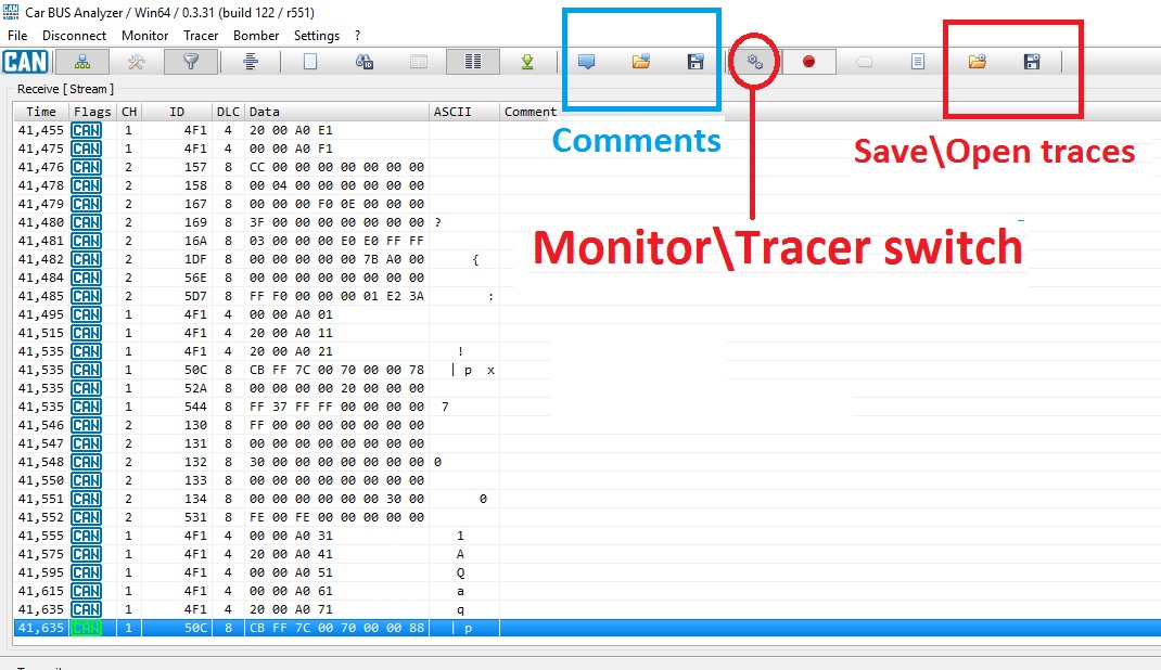
To save and download trases, the buttons in the top menu are extremely right, marked with a red rectangle in the photo above. (Folder and Diskette)
You can make, save and load comments for each CAN frame. See icons in the blue rectangle.
To switch to CAN monitor mode, click the Monitor button in the top menu.
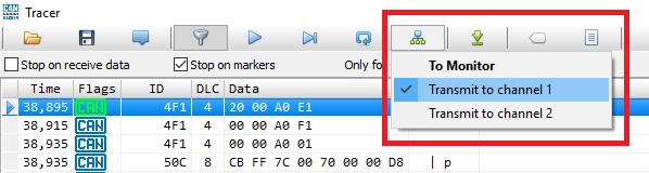
To play saved Trace, click Tracer at the top of the menu
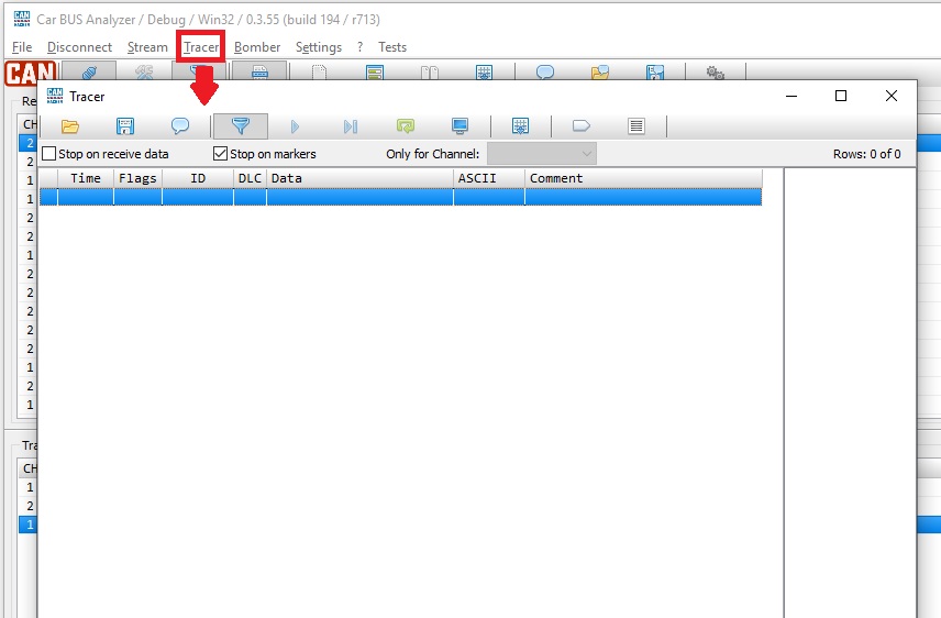
In the opened window, download the saved stream file (trace) and select the channel from the Only for Channel list that will be used in the work. This is necessary in case the flow was recorded from two channels at the same time.
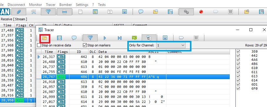
Select which channel you want to transfer frames from the saved thread as in the figure above. If you select the To Monitor option, frames from the trail will be broadcast through the monitor window and will not be physically transmitted to the CAN bus.
With the Play Stop, Step and Repeat buttons, which have the corresponding graphics in the top menu, you can control the stream playback.
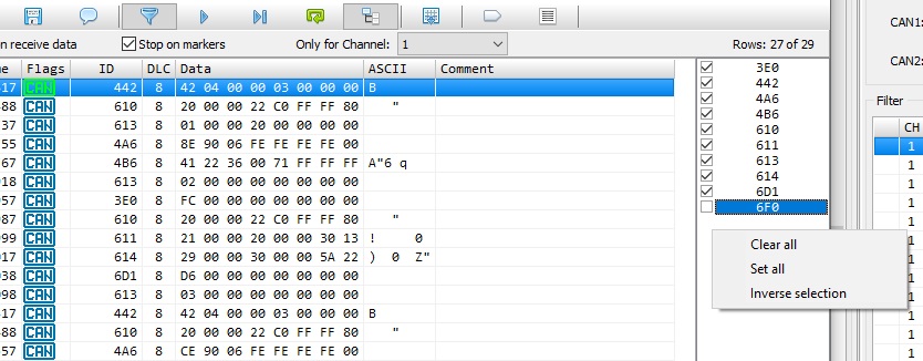
In the right hand side of the track window, you can mark the ID of the frames you want to play.
Right clicking on this window allows you to perform group operations with the ID table.
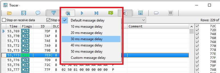
To control the playback rate of the Trace, press the timer icon as in the image below and select the required delay between the frames.
CAN Gateway mode
The CAN gateway (CAN Gateway) mode is available for two-channel CAN interfaces.
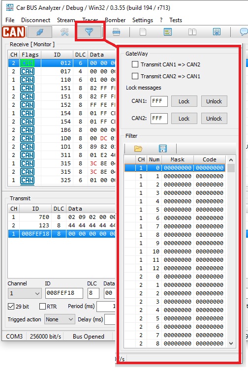
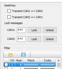
The CAN gateway settings are on the CAN filter configuration tab.
- Transmit CAN1=>CAN2 flag involves transferring frames from channel 1 to channel 2.
- Transmit CAN2=>CAN1 flag involves transferring frames from channel 2 to channel 1.
- Lock messages – unactived function now. It is for future.
CAN Bomber
CAN Bomber is a built-in tool for brute forcing on the CAN-bus. To enter Bomber mode, click Bomber in the top CARBUS Analyzer menu
После чего в нижней части формы откроется сам Bomber
![]()
In the ID from and To fields, the ID search range is set. To run 29 bit Ids, you need to set the 29 bit flag just below the Channel drop-down list.
Bomber mode is set in the drop down list Mode. The following modes are available:
- ID Counter – increment ID over 1
- ID List – by ID table
- Data counter – Fixed ID, brute force data bytes
- Data counter with shift – brute force data bytes with shift.
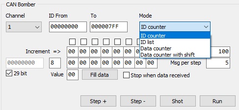
The easiest mode is ID Counter.
In this mode, the fixed data frame and the ID overhaul are transmitted in the specified range with increment ID+1.
The more complex mode is the ID List. In this mode, the fixed data frame transfer is done with the ID of the Unique ID List, which is the list of Ids to be searched. You can add an ID to a table manually, from a file, or copy all the ID from the Receive Monitor window. The Unique ID List is the right-click on the Unique ID List
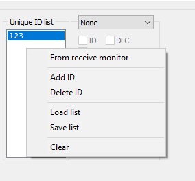
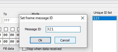
To manually add an ID, press Add ID. To remove – Delete ID
To add ALL ID from the received frames window in the drop-down menu, select From Receive monitor
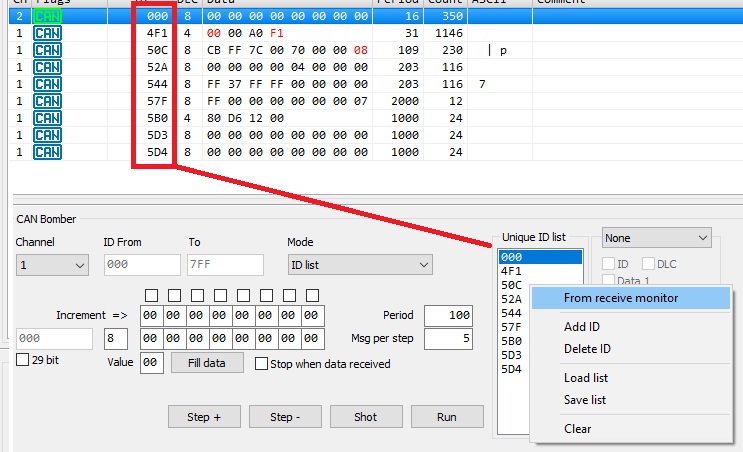
The BruteForce starts when the Run button is clicked. The BruteForce occurs with the period specified in the Period field. With each ID, the number of frames specified in the Msg per step field is transferred.
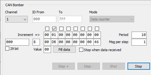
Data counter or Data counter with shift is selected to parse the data.
In Data counter mode, a fixed ID frame and an increment of flagged bytes of data are sent. Increment is performed by the value specified in the string Increment=>, individually for each data byte.
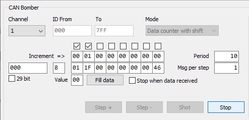
In Data counter with shift mode, the increment to the specified value of the noted bytes of data is performed. If the more right-marked byte passes through the FF, then increment to +1 observed byte to the left. So you can go through all the possible combinations of bytes of data in the frame.
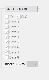
In Bomber mode, you can calculate the checksum of the frame – CRC. The checksum is applied on many cars and if it is not correct, the frames transferred are ignored. Different manufacturers may have different CRC calculation algorithms. Bomber has two calculation algorithms available: Toyota (universal) and ISO J1850. The CRC mode is set in the menu to the left of the Unique ID list.
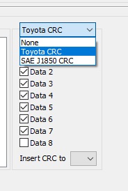
In Toyota CRC mode, all the noted elements of the frame are added to module 2. The resulting value is inserted into the data byte selected in the drop-down list Insert CRC to.
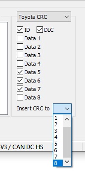
In ISO J1850 mode, the calculation is carried out automatically and the value is transmitted to the eighth byte of data of the transferred frame.