Please, read it up to end!
The CARBUS analyzer and your interface don’t require activation!
- Install drivers
- Download CARBUS analyzer archive, unpack it
- Run CarBUSAnalyzer.exe
- If you have the activated CAN-Coder option see this article
Driver installation
You have to install a virtual COM port driver by ST-Microelectronics before working.
Download
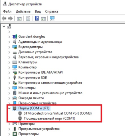
After installing the driver and connecting the interface to the computer, a device “STM Virtual Com Port” should appear in the Ports section. The port will be assigned a number, for example COM3, as in the screenshot below. The port number will need to be entered in the CARBUS Analyzer program when connecting to the interface, so remember this number.
Download and run software
You can download CARBUS Analyzer software on the Download page.
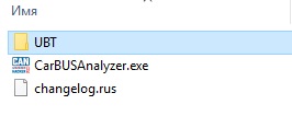
Unpack the downloaded archive.
The software archive contains:
- CARBUS Analyzer
- UBT firmware update utility
- Firmware files
Configure CARBUS Analyzer and CAN bus interface
Click the Settings menu
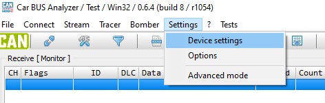
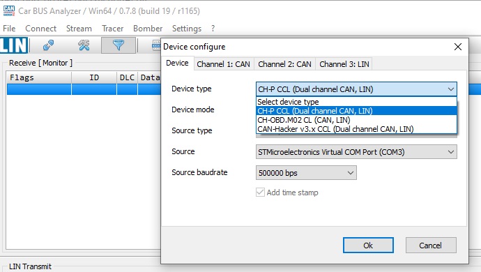
- Device type – CH-P CCL (CAN CAN LIN = CCL)
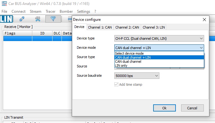
- Device mode – CAN, CAN+LIN or LIN only
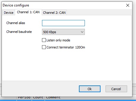
Configure CAN channels
CAN channels are configured on the Channel 1: CAN and Channel 2: CAN tabs.
These tabs become visible after you select the interface mode to work with the CAN bus.
- Channel baudrate – sets the CAN bus speed.
- Listen only mode – Switch CAN interface to “Listen only” mode, which loses the ability to send frames, but when receiving frames across the bus, the interface does not flag the acknowledgement of ACK reception on the bus, making the interface invisible to other devices on the bus.
- Connect terminator 120 Ohm – connecting the 120 Ohm resistor between CAN-High and CAN-Low for each channels
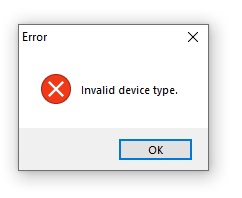
Invalid Device type message will appear if the interface type is not correctly defined or if it is loaded with an obsolete firmware
CAN bus connection
The CAN bus is connected with the interface cable
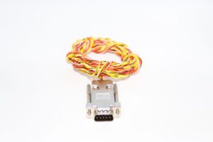
- Yellow\black– CAN-Low channel 1
- Yellow\white– CAN-High channel 1
- Orange\black – CAN-Low channel 2
- Orange\white – CAN-High channel 2
When connecting to a single-wire bus CAN (SWCAN – Single Wire CAN, GMLAN), it is necessary to connect the CAN-Low wire to the mass (GND) of the tested car or control unit, and the CAN-High wire to the SWCAN GMLAN line.
If the CAN settings are done correctly, the physical connection to the bus is correct and the bus is exchanged, then the CAN bus data will be displayed in the receiving window after pressing the Connect button.
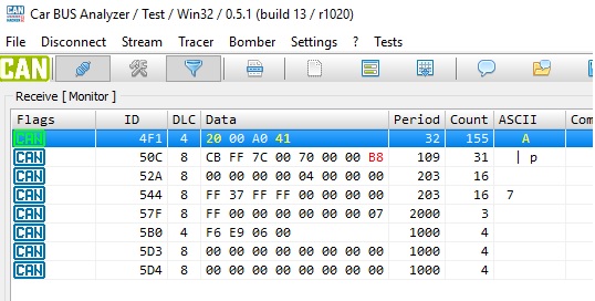
A detailed description of the work with CARBUS Analyzer as CAN bus analyzer is available on this page .
LIN bus analyzing
Configure interface:
- Click Settings
- Device type: CH-P CCL
- Device mode: CAN dual channel+LIN or LIN only
After interface configuration:
- Setings -> Channel 1: LIN.
- Channel baudrate -> LIN bus baudrate
- Detection time – > a minimal pause between LIN frames. 2ms – default
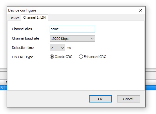
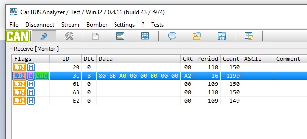
The LIN CRC Type parameter defines the type of checksum method used when working with a LIN bus. This option does not affect the ability of the interface to accept frames. If the checksum type is not correctly defined, then the receiving party will ignore the frames when passing through the interface.
LIN Bus Cable (Optional)
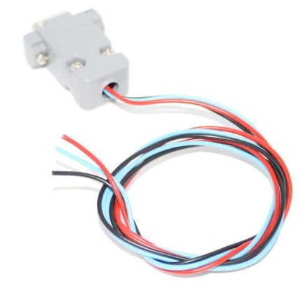
- Red – +12 V
- Black – GND
- Blue – LIN
Important! LIN bus requires GND and +12V connection !
If the connection and settings are done correctly and the LIN bus is active, i.e. data is exchanged between the Master and Slave nodes or queries are received from the Master node, then the LIN bus data is displayed in the reception window.
A detailed description of the work with CARBUS Analyzer as a LIN bus analyzer can be found on this page.