Please! Read it up to the End
The CARBUS analyzer and your interface don’t require activation!
- Install drivers
- Download CARBUS analyzer archive, unpack it
- Run CarBUSAnalyzer.exe
Driver installation
Before you can use the device, you must install the STM virtual COM driver if it has not been installed previously.
Download
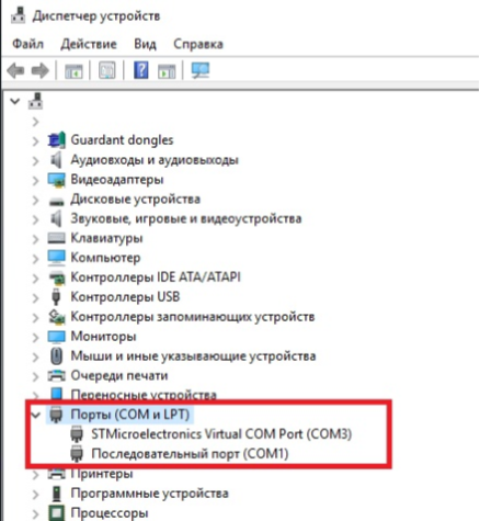
After installing the driver and connecting the interface to the computer, the “STM Virtual Com Port” device should appear in the Ports (COM and LPT) section of the Device Manager. The port will be assigned a number, for example COM3, as shown in the screenshot below. The port number will need to be entered in the CARBUS Analyzer when connected to the interface, so note this number.
Driver installation problems and solutions
Driver installation issues may occur on older versions of Windows XP and Windows 7.
The interface in the dispatcher is defined as a virtual COM port, but when trying to connect to it, the software hangs or gives an error. In this case, please note that two driver versions are available for download on our site and you should try to install a driver version other than the one that was first installed. This usually helps to solve the problem.
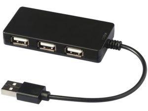
The second problem may be the low speed of the interface. In this case, the received packets are displayed with a clear delay. This may be due to an older USB controller on your computer. The use of an external USB hub (splitter) that matches the size of the interface packages and the USB controller on the motherboard of the computer will help solve the problem.
To use CH-OBD.M02 as a can and LIN Bus Analyzer, you need to download the CARBUS Analyzer software from the download page.
Then unpack the downloaded archive.
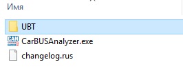
THE archive contains both the CARBUS Analyzer and the UBT firmware update utility (UBT folder) with a folder containing the latest firmware files (UBT\Firmware files)
Configure the CARBUS Analyzer and can interface
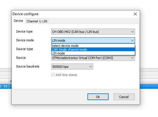
IN the CARBUS Analyzer, in the Settings menu, select the interface type – CH-OBD.M02 from the Device Type drop-down list.
IN the Device mode drop-down list, you must select the can Single channel mode.
SELECT a port from the Sourcedrop-down list, on which the interface is defined in the system.
CAN channel setup
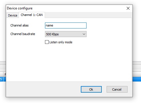
The CAN channel is configured in Channel 1 CAN: This tab becomes visible after the interface mode is selected for can bus operation.
Channel budget – Sets the speed of CAN-bus operation.
Listen only mode flag – sets the interface to listen only mode, In which the ability to send packets is lost, but when packets are received on the bus, the interface does not flag the ACK acknowledgment on the bus, which makes the interface invisible to other devices on the bus.
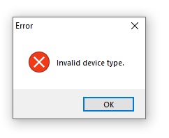
IF the interface type is not specified correctly or if an outdated firmware is loaded, an Invalid Device type message appears
Can bus connection
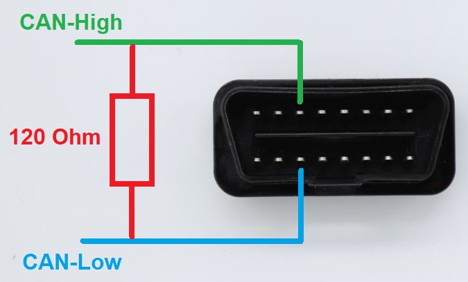
Physical connection to the CAN-bus is made through pins 6—CAN-High and 14—CAN-Low of the external interface connector. Ground connection (GND) is optional when connected to the two-wire can bus.
The CH-OBD.M02 interface does not have an internal 120 ohm resistor-terminator between the CAN-High and CAN-Low lines, so there may be no can communication when connected to individual control units on the table, In this case, it is necessary to connect a 120 Ohm resistor between the CAN-High and CAN-Low lines.
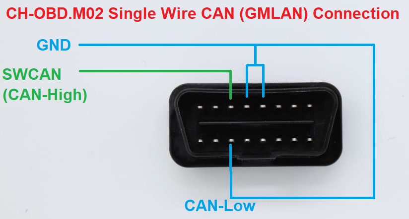
When connected to a single-wire CAN-bus (SWCAN), such as GMLAN, the CAN-Low line of the interface must be connected to ground, with the ground of the device or vehicle and interface being examined connected to each other as well. The CAN-High line of the interface is then connected to the single wire CAN-bus (GMLAN).
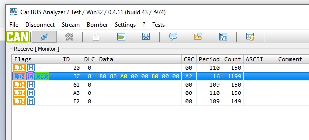
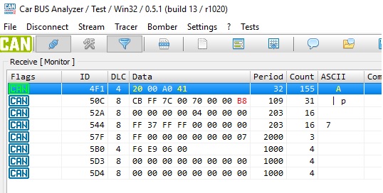
If the CAN-bus settings are correct, the physical connection to the bus is correct and there is communication on the bus, the can bus data will be displayed in the reception window after the Connect button is pressed.
Working with the LIN bus
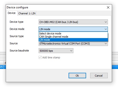
To operate the LIN bus, the can-Hacker 3.2 interface must be put into the LIN Bus Analyzer operating mode. This requires:
Access the Settings menu
- IN the Device type drop-down list, select CH_OBD.M02
- In the Device mode drop-down list, select LIN mode
- In the Source drop-down list, select the port on which the system has defined the interface.
After selecting the interface type and mode, you must:
- Go to Channel 1: LIN tab. Which is activated after selecting the LIN mode on the previous Device tab.
- IN the Channel baudrate drop-down list, select the LIN bus speed
- IN the Detection time drop-down list, select the minimum expected pause between packages. It is recommended to keep the default value –2 milliseconds.
- Select a checksum type. If the type is not specified correctly, it is fine, it does not affect packet reception.
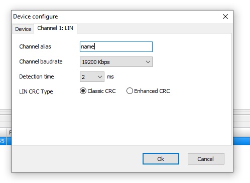
The LIN CRC Type parameter determines the type of method used to calculate the checksum when working with the LIN bus. This setting does not affect the ability of the interface to receive packets. IF the checksum type is not specified correctly, then when passing packets through the interface, the receiving party will ignore these packets.
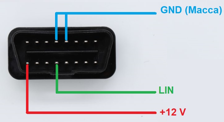
LIN bus connection
Caution: Be sure to connect GND and 12V
If the connection and settings are correct and the monitored LIN bus is active, i.e. the master and slave nodes are communicating with the device or requests are received from the master node, the receive window will display the LIN bus data.