Please, read it up to end!
- Install drivers
- Download CARBUS analyzer archive, unpack it
- Run CarBUSAnalyzer.exe
Driver installation
You have to install a virtual COM port driver by ST-Microelectronics before working.
Download
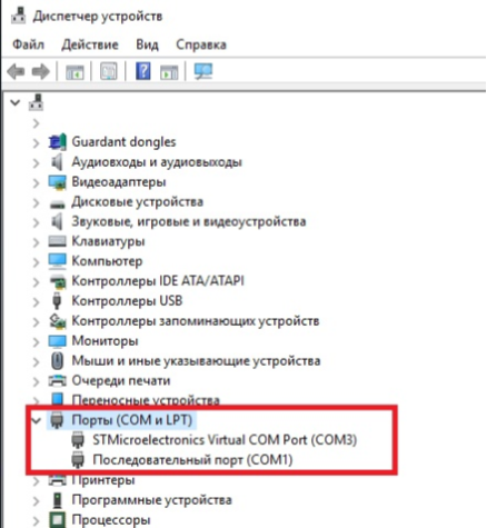
After installing the driver and connecting the interface to the computer, a device “STM Virtual Com Port” should appear in the Ports section. The port will be assigned a number, for example COM3, as in the screenshot below. The port number will need to be entered in the CARBUS Analyzer program when connecting to the interface, so remember this number.
Possible problems in installing the driver and how to solve them
Problems with driver installation can occur on older versions of Windows XP and Windows 7. The interface is defined in the manager as a virtual COM port, but when you try to connect to it, the software hangs on or fails. In this case, please note that there are two drivers available for download on our site, and try to install a different driver version from the one that was installed first. This usually helps to solve the problem.
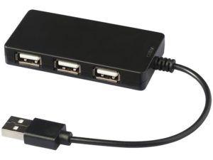
The second problem may be the low speed of the interface. In this case, the received packets are displayed with a clear delay. This may be due to the fact that the USB controller is obsolete on the computer. The solution is to use an external USB hub (Splitter) that agrees the size of the interface packets and the USB controller of the motherboard.
Working with CAN\LIN
To work with the CAN-Hacker 3.2 interface as the CAN and LIN tire analyzer it is necessary to download the CARBUS Analyzer software on the DOWNLOAD page.
Then unpack the downloaded archive.
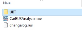
The archive contains both the CARBUS Analyzer program itself and the UBT firmware files (UBT folder) upgrade utility from the current firmware files (UBT Firmware files) folder
Configure CARBUS Analyzer and CAN bus interface
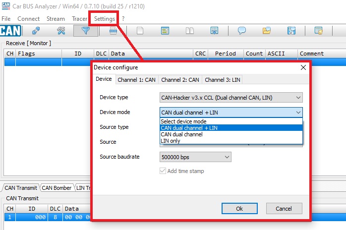
- Click Settings in the CARBUS Analyzer Top menu
- Device type – CAN-Hacker v3.x CCL
- Device mode – CAN dual channel or CAN dual channel+LIN \ LIN Only if you have an activated LIN option
- Source – Virtual COM port (See Windows Device manager)
- Source baudrate – don’t touch it.
Configure CAN channels
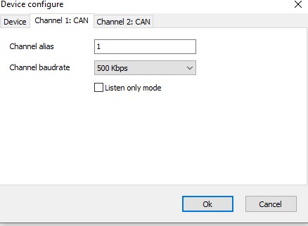
- CAN channels are configured on the Channel 1: CAN and Channel 2: CAN tabs. These tabs become visible after you select the interface mode to work with the CAN bus.
- Channel baudrate – sets the CAN bus speed.
- Listen only mode – Converts the interface to Listen only mode, which loses the ability to send frames, but when receiving frames across the bus, the interface does not flag the acknowledgement of ACK reception on the bus, making the interface invisible to other devices on the bus.
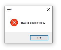
Invalid Device type message will appear if the interface type is not correctly defined or if it is loaded with an obsolete firmware
CAN bus connection
The CAN bus is connected with the interface cable
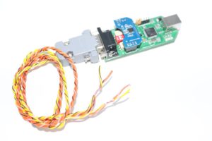
- Yellow\black– CAN-Low channel 1
- Yellow\white– CAN-High channel 1
- Orange\black – CAN-Low channel 2
- Orange\white – CAN-High channel 2
Switches description
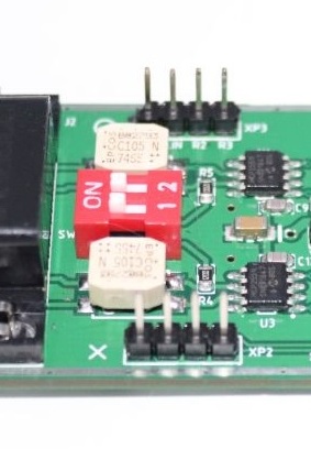
The DIP switch – Connect the 120 Ohm terminator for each CAN channel
If the CAN settings are done correctly, the physical connection to the bus is correct and the bus is exchanged, then the CAN bus data will be displayed in the receiving window after pressing the Connect button.
A detailed description of the work with CARBUS Analyzer as CAN bus analyzer is available on this page.
LIN bus analyzing
(LIN bus adapter must be installed and activated)
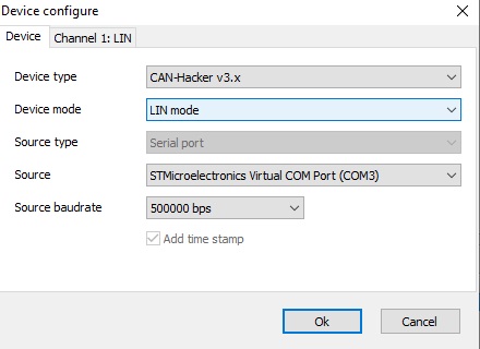
Configure interface:
- Click Settings
- Device type – CAN-Hacker v3.x
- Device mode – LIN mode
- Source – COM port of the interface
After interface configuration:
- Setings -> Channel 1: LIN.
- Channel baudrate -> LIN bus baudrate
- Detection time – > a minimal pause between LIN frames. 2ms – default
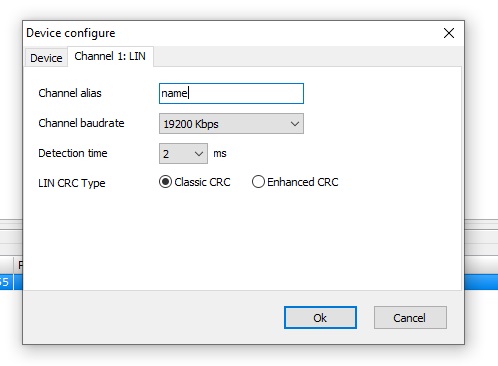
The LIN CRC Type parameter defines the type of checksum method used when working with a LIN bus. This option does not affect the ability of the interface to accept frames. If the checksum type is not correctly defined, then the receiving party will ignore the frameswhen passing through the interface.
The LIN bus is connected by the LIN analyzer cable supplied with the option.
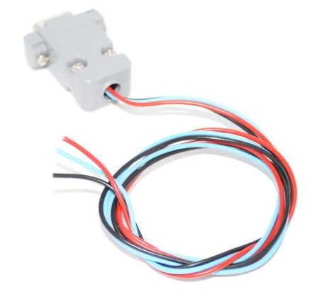
- Red – +12 V
- Black – GND
- Blue – LIN
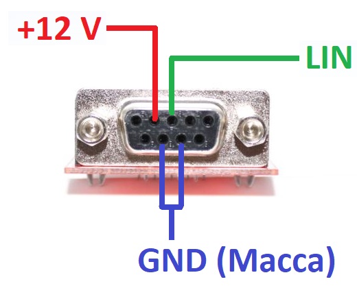
Important! The connection to the LIN bus of the tested device or car requires a mandatory GND connection and a power supply of +12 V.
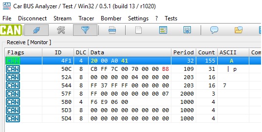
If the connection and settings are done correctly and the LIN bus under study is active, i.e. data is exchanged between the Master and Slave nodes or queries are received from the Master node, then the LIN bus data is displayed in the reception window.
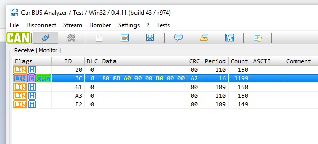
A detailed description of the work with CARBUS Analyzer as a LIN bus analyzer can be found on this page.